IC MTRDRV BIPLR 4.5-36V 16PWRDIP
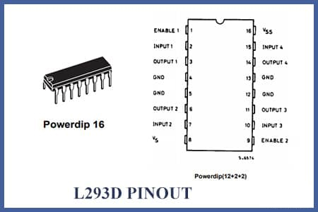
L293D is a push-pull four-channel driver with diodes. This blog mainly introduces pinout, specifications, applications, and other detailed information about STMicroelectronics L293D.

IC MTRDRV BIPLR 4.5-36V 16PWRDIP L293D is a push-pull four-channel driver with diodes. This blog mainly introduces pinout, specifications, applications,
49
Feb 23, 2021
Muriel
IC MTRDRV BIPLR 4.5-36V 16PWRDIP
L293D is a push-pull four-channel driver with diodes. This blog mainly introduces pinout, specifications, applications, and other detailed information about STMicroelectronics L293D.
L293D
| Quantity | Unit Price | Ext. Price |
|---|---|---|
| 1+ | $4.94153 | $4.94 |
| 10+ | $4.66182 | $46.62 |
| 100+ | $4.39794 | $439.79 |
| 500+ | $4.149 | $2074.5 |
| 1000+ | $3.91415 | $3914.15 |
The L293D is a monolithic integrated high voltage, high current four channel driver designed to accept standard DTL or TTL logic levels and drive inductive loads (such as relays solenoides, DC and stepping motors) and switching power transistors. To simplify use as two bridges each pair of channels is equipped with an enable input. A separate supply input is provided for the logic, allowing operation at a lower voltage, and internal clamp diodes are included. This device is suitable for use in switching applications at frequencies up to 5 kHz. The L293D is assembled in a 16 lead plastic package which has 4 center pins connected together and used for heatsinking.
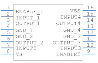 PCB Symbol - STMicroelectronics L293D
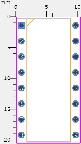 PCB Footprint - STMicroelectronics L293D
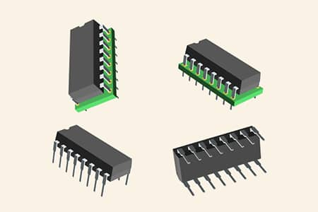 3D Model - STMicroelectronics L293D
600mA OUTPUT CURRENT CAPABILITY PER CHANNEL
1.2A PEAK OUTPUT CURRENT (nonrepetitive) PER CHANNEL
ENABLE FACILITY
OVERTEMPERATURE PROTECTION
LOGICAL "0" INPUT VOLTAGE UP TO 1.5 V (HIGH NOISE IMMUNITY)
INTERNAL CLAMP DIODES
STMicroelectronics L293D technical specifications, attributes, parameters and parts with similar specifications to STMicroelectronics L293D.
STMicroelectronics L293D technical specifications, attributes, parameters and parts with similar specifications to STMicroelectronics L293D.
| Product Attribute | Attribute Value | |
|---|---|---|
| Lifecycle Status | ACTIVE (Last Updated: 7 months ago) | |
| Factory Lead Time | 10 Weeks | |
| Mount | Through Hole | |
| Mounting Type | Through Hole | |
| Package / Case | 16-DIP (0.300, 7.62mm) | |
| Number of Pins | 16Pins | |
| Manufacturer Package Identifier | Powerdip 16 | |
| Operating Temperature | -40°C~150°C TJ | |
| Packaging | Tube | |
| JESD-609 Code | e3 | |
| Part Status | Active | |
| Moisture Sensitivity Level (MSL) | 1 (Unlimited) | |
| Number of Terminations | 16Terminations | |
| ECCN Code | EAR99 | |
| Terminal Finish | Tin (Sn) | |
| Applications | General Purpose | |
| Voltage - Supply | 4.5V~36V |
| Product Attribute | Attribute Value | |
|---|---|---|
| Terminal Position | DUAL | |
| Supply Voltage | 5V | |
| Base Part Number | L293 | |
| Function | Driver - Fully Integrated, Control and Power Stage | |
| Max Output Current | 1.2A | |
| Operating Supply Voltage | 24V | |
| Number of Channels | 4Channels | |
| Interface | Parallel | |
| Operating Supply Current | 2mA | |
| Output Configuration | Half Bridge (4) | |
| Power Dissipation | 4W | |
| Output Characteristics | 3-STATE | |
| Output Current per Channel | 600mA | |
| Collector Emitter Voltage (VCEO) | 36V | |
| Max Collector Current | 600mA | |
| Output Polarity | TRUE | |
| Input Characteristics | STANDARD |
| Product Attribute | Attribute Value | |
|---|---|---|
| Voltage - Load | 4.5V~36V | |
| Output Peak Current Limit-Nom | 1.2A | |
| Supply Voltage1-Nom | 24V | |
| Min Supply Voltage (DC) | 4.5V | |
| Built-in Protections | TRANSIENT; THERMAL | |
| Motor Type | Brushed | |
| Output Current Flow Direction | SOURCE SINK | |
| Motor Type - AC, DC | Brushed DC | |
| Motor Type - Stepper | Bipolar | |
| Height | 5.1mm | |
| Length | 20mm | |
| Width | 7.1mm | |
| Radiation Hardening | No | |
| RoHS Status | ROHS3 Compliant | |
| Lead Free | Lead Free |
• Stepper Motor Drivers
• DC Motor Drivers
• Latching Relay Drivers
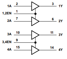 Logic Diagram
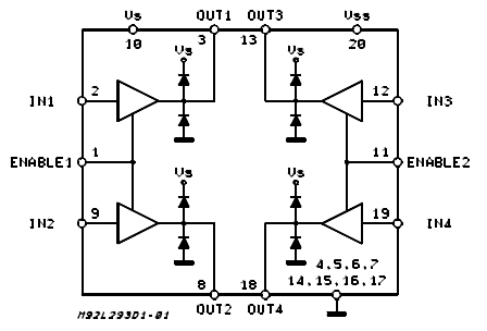 BLOCK DIAGRAM
LB1909MC, SN754410, ULN2003
It's very simple to use the L293D motor driver IC. The IC operates on the Half H-Bridge principle; we won't go into too much detail about what that means; for now, just know that a H bridge is a setup that can operate motors both clockwise and anticlockwise. As previously mentioned, this IC is capable of simultaneously driving two motors in either direction; the circuit to accomplish this is shown below.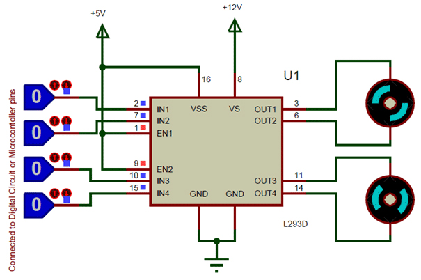 circuit using L293D motor driver IC
All of the Ground pins should be connected to the ground. The Vss(Vcc1) power pin must be wired to +5V. The other power pin for this IC is the Vss(Vcc1) power pin, which provides the voltage for the IC to operate. The other pin is Vs(Vcc2), which provides voltage for the motors to operate. Depending on your motor's specifications, you can connect this pin to anywhere between 4.5V and 36V, but I've connected it to +12V here.
Enable pins (Enable 1,2 and Enable 3,4) are used to enable Motor 1 and Motor 2 input pins, respectively. Since we will be using both motors in most situations, both pins are kept high by default by connecting to the +5V supply. The motor 1 is controlled by input pins 1,2 and the motor 2 is controlled by input pins 3,4. To control the speed and direction of the motor, the input pins are connected to any digital circuit or microcontroller. To power your motor, toggle the input pins according to the table below.
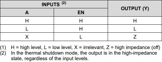 Function Table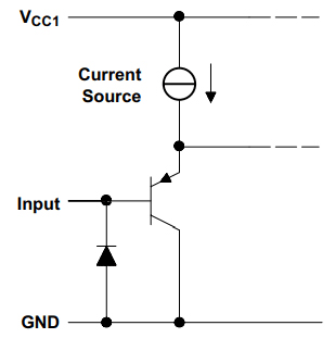
Schematic of Inputs for the L293x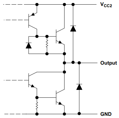 Schematic of Outputs for the L293D
 Layout Diagram
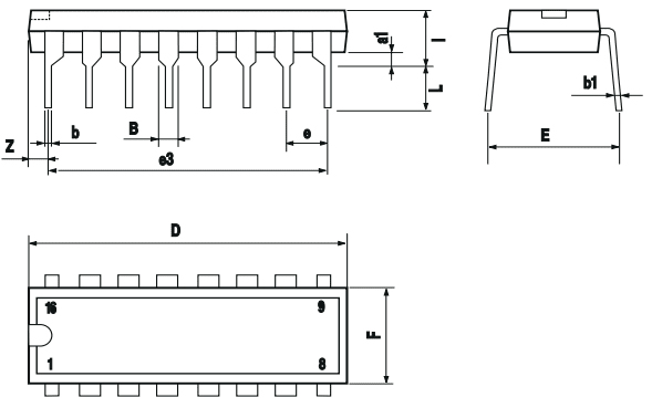 OUTLINE
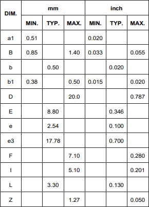 MECHANICAL DATA
STMicroelectronics is a global independent semiconductor company and is a leader in developing and delivering semiconductor solutions across the spectrum of microelectronics applications. An unrivaled combination of silicon and system expertise, manufacturing strength, Intellectual Property (IP) portfolio and strategic partners positions the Company at the forefront of System-on-Chip (SoC) technology and its products play a key role in enabling today's convergence trends.
Download datasheets and manufacturer documentation for STMicroelectronics L293D.
Download datasheets and manufacturer documentation for L293D
TAGS
Comments